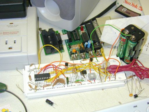
After finishing both temperature and clock projects on the basic stamp board, I was ready to get to work on my clock project using the PIC16F628 chip. I had bought the EPIC programmer from microEngineering Labs which, while simple, is a reliable programmer to use to get started on PIC programming. Seems to be a bug in the drivers though... on WinXP, the printer port stays open after printing with no way to close it, so I need to re-boot before I can use the EPIC programmer again. Oh well.
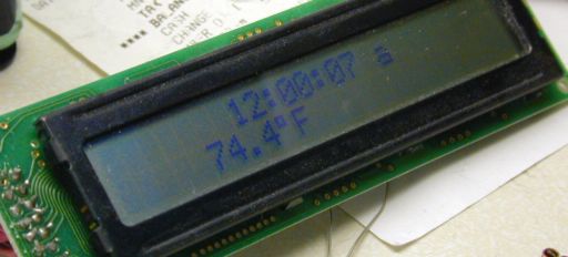
Coding the LCD routines was the next difficulty. After a missed return statement, I got it displaying a message. I set up timer 0 to generate interupts at 1 second intervals, and coded a routine to increment time by one second and display it on the LCD. This involved a divide routine, which you'll find somewhere in my code. It's messy code, but then again, I never bothered to optimize anything. I also added two buttons on port A and a new section of the start-up routine such that it will display the time and let you use the two buttons to set the time.
Now, to also read the temperature. This requred a few more routines so i could do 16 bit math. This took forever... while the 8 bit divide routine i wrote in the previous section worked like a charm first time, the 16 bit multiply routine refused to work for days. After various poking and proding, it one day began working after some change I made that I can't remember. How to avoid this in the future? Remember that programming isn't like riding a bike... you DO forget the basic stuff. I'm sure I had inverted a bit test or shifted the wrong way or something. And document the code. By the 3rd day of testing the routine, I already started to forget what each line did.
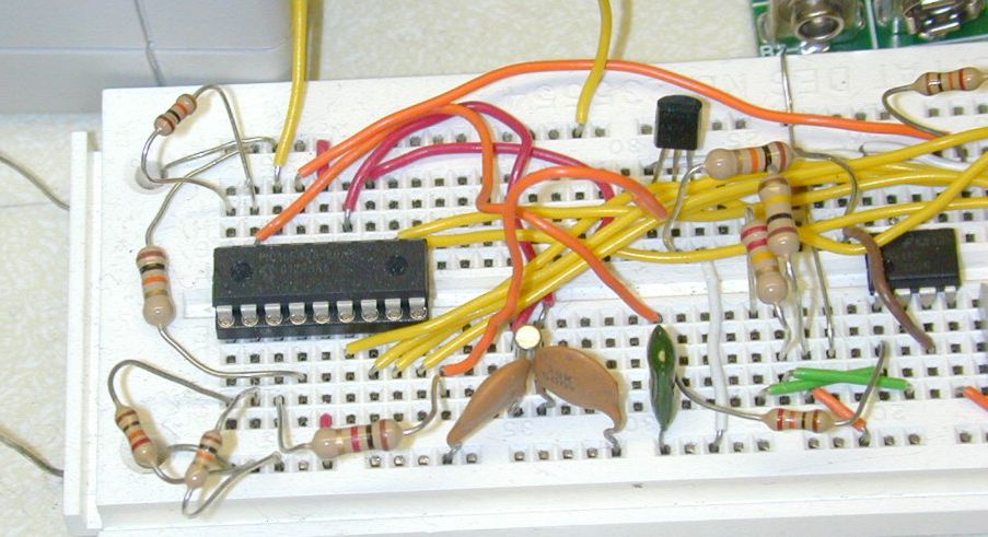
Initial tests showed that the two resistor-one capacitor sampling system wouldn't work with the temperature directly. To make the voltage a bit more 'convenient', I wired an Op-Amp in to multiply the LM34 voltage output. Several more issues with sampling later, I discovered to just get two digits of precision with this method would require at least 3 seconds to sample... and I was planning to sample this between second interrupts. Dang...
So, back to the drawing board. My solution was to use the internal RC resistor as the main clock and put the XTAL on the timer1 oscilator. Perfect... Except this meant re-timing the LCD routines. No problem... Just add wait macros. Done. Tweak timer1 to interupt at 0x8000 (32768, the xtal freq) counts by adding 0x8000 every interupt. Done. Use smaller cap to speed up RC sampling of temperature sensor. Done. I now have 3 digits of precision and takes 1/10th of a second to sample.
I had initially wanted to power the unit off of solar cells. By sleeping between interupts, the chip draws less than 100uA on average, but the LCD unit draws about 2mA. There goes the solar power. The cells can push that in direct sunlight, but in the shade they can barely manage, and indoors, forget about it. The half-farad cap i'd ordered from Radio Shack would only power it for about a half hour maximum before the voltage would be below LCD minimum. J-term is about over -- the clock thermometer works but requires a lot of power. Would only last a month on rechargable batteries, 3 months or so on alkaline. If it turned itself off at night, maybe 4-5 months. Not good enough. My wrist watch lasts longer than that.
code: picclock.asm
schematic: here
pictures: