Okay. Now i have an LCD display. What am i going to do with it? Clocks are obvious, but if you plan to do a clock with a BS2 chip alone, be ready for an error of an hour a day. Or a lot of math. BS2 instruction execution time is a topic i've never investigated, and the stats i've seen before had a huge margin of error. There are better ways to keep time anyways, and i'll explain that next project.
I happened to have an LM34 farenheit temperature sensor lying around, so i figured i should use it before it goes stale or something. The reason for the farenheit, in case you don't know, is that it outputs a voltage that, multiplied by 100, is the temperature in farenheit. The only thing you need to do is perform the analog to digital (A/D) conversion.
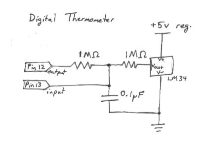
schematics: here
The BS2 doesn't have analog ports, only digital. But that doesn't mean it doesn't have an A/D converter.... a binary port IS an A/D converter, but only one bit. If you hook a resistor and cap in series to ground, and try the following program, you can use a meter to measure the crossover voltage... the voltage where the BS2 decides the voltage is high enough to be a 1 instead of a 0. Then we'll have a basic 1 bit A/D
loop:
dir13 = 0	;input on pin 13
out13 = ~in3	;invert the measured voltage
dir13 = 1	;output
pause 3		;pause
goto loop	;start over
That code will have the BS2 constantly try to get the voltage to the crossover point. Chances are it will vary chip to chip... there is supposed to be a "null" zone, but in practice, this "averages" out and it acts as if it's a fixed cutoff with some uniform noise. If you sample long enough, this "noise" won't cause problems.
On my BS2, i registered 1.458 volts. This is measured across the series resistor-capacitor combo.
On the schematic, you'll see two 1M resistors, and one 0.1 uF (microfarad) capacitor. These values were chosen to minimize power consumption. If you use lower resistance, you need a higher cap. I chose 1M to minimize power use and so that the input pin won't be affected by the voltages when sampling. However, 1K and 10uF should work with the same and allow you to use the output pin as an input pin (but you'd have to fudge the math more to get the right output).
Anyways, this two resistor voltage divider will average the inputs to the capacitor: one is the sampled voltage (the LM34) and the other is the BS2 output, in my example on pin 13 (with pin 12 for sampling). By always outputing the OPPOSITE of what is sampled, the cap will stay at a nominal 1.458 volts (or the crossover voltage on your chip). However, for every mV the LM34 goes down from 1.458, the average output from the stamp will have to go UP the same amount for the average to stay at 1.458.
The only question is how we know the output of the BS2. Wait, we're in control of the BS... lets just count how many times we output a 1 while sampling. the average voltage will be 5 * TimesOutputIsOne / IterationsOfSample. Here is some example code:
i            var word
SAMPLELENGTH con 2000  'must be multiple of 1000, or change math
SamplePin    con 12
TempPin      con 13
temperature  var word

temperature = 0

for i = 1 to SAMPLELENGTH
	outs.bit0(TempPin) = ~ins.bit0(SamplePin)   	'always output opposite
	temperature = temperature + (outs.bit0(TempPin))
next
THRESHHOLD	con	1458		'input pin threshold
i = temperature
i = ((5 * i) / (SAMPLELENGTH/1000))	'should be number of mV
temperature = 2*THRESHHOLD - i
debug ?temperature
You'll only get an accurate reading the second time through. Since the Cap has to be at the crossover at the begining of the loop, you'll need to sample twice, the first time just to get the cap to the right voltage.
So, after that loop, temperature should equal 762 for me (because it's 76.2 degrees farenheit, and my meter says 762mV when i check the LM34 output). But i get 834. What's wrong? Well, it's a real world. Things aren't always perfect, and my math probably leaves out higher order effects that the PWM has* (the voltage output isn't exactly CyclesOn/CyclesTotal). Oh well. I just subtract the difference to get it calibrated. 1 degree error per 10 degrees off of room temp isn't good, but i'm usually measuring room temperature.
If you need more accuracy, put it in two known temperatures, one after another, reading off the measured temperature. Then adjust it linearly. Bingo. Just a bit of algebra and you'd be set.
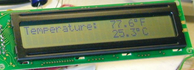
I used the code and setup of my LCD experiment for this one, threw in a routine to display the temperature (in both farenheit and celsius) and i'm done. The main routine is an infinite loop that calls the temperature sample routine, and then the display routine. The display routine simulates a cursor drawing the temperature. It's quite nifty if you ask me. It also displays a temperature trend indicator using custom characters.
I personally think that getting about 10 bits of precision out of a basic stamp chip is pretty great, even if it takes about 4 seconds to sample. Maybe some experimentation with different caps and resistors will yeild greater accuracy.
Sorry for lack of comments in my code. Maybe someday i'll fix them all.
code: LCDtemp.bs2
schematics: here (correction, that should be a 1.0uF capacitor. my bad).
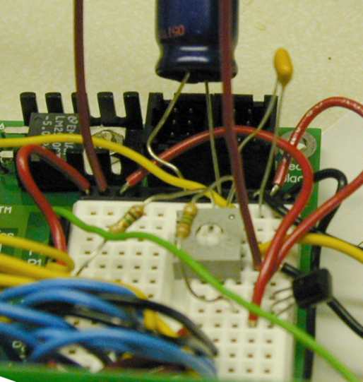
pictures: